
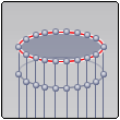
MUDBOX
H-Hide
U-Show
Middle mouse-Pan
W Show mesh
A Find lost model (when you zoom way out)
Other basics:
Joint tool:


Step for acquiring Free student version of Mudbox
1. Go to Autodesk.com
2. Scroll down to the bottom of the page
3. Find Student Downloads in the Products Section
4. Choose the Software you wish to Download
5. Sign in or Create an Account
6. Choose version, Operating System, and Language
7. Install
8. Repeat if needing more than one program
KEYBOARD SHORTCUTS
Action
|
Windows and Linux
|
Mac OS X
|
Results
|
|---|---|---|---|
| Adjust brush size | B + drag | B + drag | The tool cursor resizes larger and smaller as you drag. |
| Adjust brush strength | M + drag | M + drag | The brush strength indicator lengthens or shortens as you drag. |
| Adjust color | Ctrl + m | Control + m | Opens the Adjust Color window. |
| Increase brush size in steps | ] | ] | Increases the size of the brush in increments. |
| Decrease brush size in steps | [ | [ | Decreases the size of the brush in increments. |
| Increase brush strength in steps | ' (apostrophe) | ' (apostrophe) | Increases the strength of the brush in increments. |
| Decrease brush strength in steps | ; | ; | Decreases the strength of the brush in increments. |
| Select tools from left to right on the current tool tray. | 0 - 9 | 0 - 9 | Press the 0 through 9 keys to select the first 9 tools on a tool tray. For more information, seeTrays. |
| Invert Function | Ctrl | Ctrl | If the current tool has an inverse function, the inverse function is applied as you sculpt or paint. |
| Activate the Smooth tool temporarily | Shift | Shift | Temporarily smooths vertices, no matter which tool is active. (Releasing the Shift key reverts to the selected tool function.) |
| Turn on the Smooth Values property temporarily to smooth color applied withFreeze or Mask. | Shift | Shift | Temporarily turns on Smooth Values when using Mask orFreeze. Releasing the Shift key reverts to regular Mask orFreeze. For more information, see Advanced properties. |
| Toggle Falloff | Ctrl + \ | Command + \ | Toggles the tools falloff property between its current and previous setting. |
| Mirror X | Shift + Alt + X | Shift + Option + X | Reflects strokes for the current sculpt or paint tool across the world space X-axis. |
| Mirror Y | Shift + Alt + Y | Shift + Option + Y | Reflects strokes for the current sculpt or paint tool across the world space Y-axis. |
| Mirror Z | Shift + Alt + Z | Shift + Option + Z | Reflects strokes for the current sculpt or paint tool across the world space Z-axis. |
| Sample color in the 3D View | I | I | Turns on the Color Picker and changes the display mode to Flat Lighting to let you copy/sample color. |
| Mirror Tangent | Shift + Alt + T | Shift + Option + T | Reflects strokes for the current sculpt or paint tool across the topological center line of a topologically symmetrical model. See also Set a topological axis. |
| Mirror Off | Shift + Alt + O | Shift + Option + O | Turns off any mirror option so that sculpt or paint tool strokes are not reflected. |
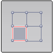
| Flatten to UV Space, Unflatten from UV Space | Alt + T | Option + T | Produces a flattened copy of a 3D model. The vertices on the flattened version are repositioned to match the UV texture coordinates of the original model to allow texture painting or basic UV editing. The original 3D version still exists and is temporarily invisible. Pressing Alt + T a second time deletes the unflattened version and displays the original 3D version with updated textures/UVs. |
Adding joints:
Other Mudbox stuff:
Maya/Mudbox:
Punching holes in Mudbox models with Maya-
1.Drop model down to level 0/Select model/File/send to Maya.
2.In Maya select a Polygon you want to use a a hole punch.
*You'll have to enlarge it a bunch because Mudbox models show up HUGE in Maya.
3.Intersect the base model and the new polygon in the area you want the hole to show up in.
4.Right click and make sure you are in object mode then using the arrow selection tool first select the base model then the intersecting polygon.
5.Mesh/Booleans/difference.
6.You can now export the model as an obj or send it directly to Mudbox by:
File/send to Mudbox
Deleting faces every time:
* This should be done at the beginning of the modeling process because it involves deleting all higher model level.
1.Select faces:
Select/move tab/faces
2.Reduce model to level 0
3.Mesh/delete highest level
4.Delete: Hit delete key or edit/delete selected.
Patching those delete faces:
1. Mesh reduce mesh by 1%: You can only patch triangular based meshes this process turns your model into triangles.
2.Select/move tools, Borders: Select a border around the hole.
3.Mesh/Patch
-Loading new "starting point" sculptures:
0. Load a new mesh from the Mudbox community (This creates the folder we need to add the new "starting point" base meshes too.
1. Shift Comand G (Opens up library menu).
2.~/Library (gets you in the Apple application library)
3.Application support (folder)/Autodesk/MudboxCommunity/Downloaded Meshes
4.Place models in downloaded meshes folder.
-Arranging the Sculpture TRAY (or any other tray)
The 1-9 keys relate to that relative position in the paint tray. To change the position of a tool middle mouse drag that tool to the position you want. Obviously you want the tools you use most in the 1-9 position.
-Changing individual "Material Presets"
Changing the default material presets (next to stamp and stencil) will change the presets of every object in your scene.
In order to change them individually you must first right click on an object and then click:
Assign new material/Mudbox Material. Once you do that you should be able to assign individual material presets.
Mesh error breakdown (and how to fix):
-Arranging the Sculpture TRAY (or any other tray)
The 1-9 keys relate to that relative position in the paint tray. To change the position of a tool middle mouse drag that tool to the position you want. Obviously you want the tools you use most in the 1-9 position.
-Changing individual "Material Presets"
Changing the default material presets (next to stamp and stencil) will change the presets of every object in your scene.
In order to change them individually you must first right click on an object and then click:
Assign new material/Mudbox Material. Once you do that you should be able to assign individual material presets.
| Problem/Error Message | Possible Solution | |
|---|---|---|
 |
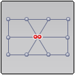
High-valence vertex
At least one vertex has more than 16 adjacent edges. You can use this mesh, but if you use it for a map extraction with Mesh Smoothing turned on, there will be artifacts in the resulting map.
|
Continuing with this mesh is fine for retopology operations, but it is not suitable for subdivision.
If you need to subdivide the mesh, you can select and delete the offending faces, then select the border and patch the hole.
|
 |
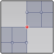
Non-manifold (T-shape)
At least one edge in this mesh is shared by more than two faces.
This must be corrected before the mesh can be used in Mudbox.
|
Select and delete the offending faces, then patch the hole. Export to Maya if the problem is difficult to fix.
|
 |
Non-manifold (vertex splice)
At least one vertex in this mesh is shared by faces that are not a part of the same fan.
This must be corrected before the mesh can be used in Mudbox.
|
Select and delete the offending faces, then patch the hole. Export to Maya if the problem is difficult to fix.
|
 |
Two-sided faces
There is at least one face in this mesh whose boundary is made up of only two edges. Using this mesh in Mudbox will cause errors when sculpting and painting.
|
Select and delete the offending faces, then patch the hole. Export to Maya if the problem is difficult to fix.
|
 |
Too many sides in a face
The boundary of at least one face in the mesh comprises more than 16 edges. This mesh will not subdivide properly, and will show visible artifacts near this face if painted.
|
Select and delete the faces, then patch the hole. Export to Maya if the problem is difficult to fix.
|
 |
Boundary Vertex has Too Many Edges
A vertex is shared by more than two boundary edges. This must be corrected before the mesh can be used in Mudbox.
|
Select and delete the corresponding faces, then patch the hole. Export to Maya if the problem is difficult to fix.
|
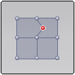 |
Interior Vertex has Valence Two
A vertex on the interior of the mesh has exactly two edges connecting it. This mesh cannot be subdivided, and will cause problems when sculpting.
|
Select and delete the corresponding faces, then patch the hole. Export to Maya if the problem is difficult to fix.
|
 |
Zero-length edges
At least one edge in this mesh is zero-length. If painted, this mesh will show visible artifacts. This can be corrected by subdividing the mesh once with Smooth Positions turned on.
|
Turn Smooth Positions on in the Subdivision Options (Mesh > Add New Subdivision Level Options), then press Shift + D to subdivide the mesh.
Smoothing out the area to make the problem faces slightly larger can also help.
|
 |
Lamina Faces
Some faces in this mesh lie exactly on top of other faces. This mesh will not subdivide properly, and will have visible artifacts if painted.
|
Turn on Display > Mesh Errors to identify where lamina faces occur.
Delete the problem faces and patch any holes.
|
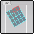 |
UV Faces Crossing Tile Boundaries
The UV coordinates of some faces on this mesh cross tile boundaries. (In Mudbox, UV tiles are bounded by integer UV values, such as 0-1, 1-2, 2-3, etc.) This mesh cannot be painted properly. To see the problem, go to the UV View tab.
|
With the problem mesh active or selected in the 3D View, select Mesh > Flatten to UV Space (Hotkey: Alt + T). With the mesh displaying flat, select the Grab brush from the Sculpt Tools tray, then drag the UV faces to be within the UV tile boundaries. See also Adjust UV positions in 2D.
|
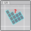 |
Incomplete UV Set
This mesh has an incomplete set of UVs. You must fix this problem before you can subdivide or paint the mesh properly. To replace the UVs, use "Create UVs in the Mesh menu.
|
Select Mesh > Create UVs from the main menu bar, then click Replace Existing UVs in the dialog box that appears. See also Create basic UVs.
|
 |
Degenerated Face
This mesh has faces where corners either lie on the same line or location in space.
|
This issue can occur in tightly detailed areas like the inner corners of the eye. The mesh can't be retopologized while this error occurs.
Select the Smooth tool from the Sculpt Tools tray (or press Shift to activate smoothing on another sculpt brush) and smooth out the area to make the problem faces slightly larger.
|
-Saving from Mudbox 2016/17-2015
- Have a finished or something you are okay with stopping at and do not need to undo. Basically where you are satisfied with the Object you have so far.
- Once you have the satisfied Object. Go to Mudbox (for MAC) or Windows for a Windows PC.
- From there go to preferences.
- Under preferences you should see a long list of tabs. Find the FBX tab.
- After you Find the FBX tab. Click on the tab and you will see a list of check boxes and one number box.
- Check to ENABLE these two options: Export ASCII FBX , Export Sculpt Layer groups as Blendshapes.
- After you enable these two options click OK.
- Select the Object.
- Once the object has been selected, go to File.
- Under file go to export.
- Under export there should be a window that pops up giving you the option to Name, Select file type, and location.
- After you have selected the Object name and location. Go to object Type.
- Select " .obj"
- Your file should be able to open in Mudbox 2015 at this point if you have saved it from 2016.
- To make sure you can open the .OBJ file in Mudbox or MAYA: Go to File>Open from there you need to click on the file to open the object.
Here is the short hand way : Windows>Preferences>FBX and activate de options: Export ASCII FBX and Export Sculpt Layer groups as Blendshapes.
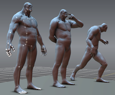
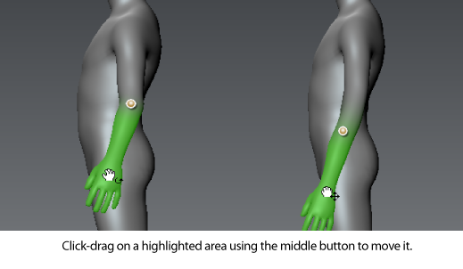
You can transform, scale, and deform models and components of models in a variety of ways using the pose tools located in the Pose Tools tray.
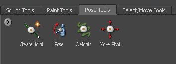
For example, if you are working with a character model you can use the posing features to place it in various types of positions and stances as well use the posing tools to deform components or change their proportions. Non-character models can be deformed and shaped just as easily by moving, bending, or twisting their components as well.
Models with skeletons rigged using other 3D applications such as Maya, 3ds Max, and Softimage can be imported to Mudbox using the FBX file format and then posed in Mudbox for a variety of purposes. For example; to perform range of motion tests to determine whether the proportions of the arms on the model allow the fingers to reach the character’s face, and so on.
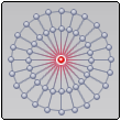
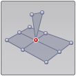
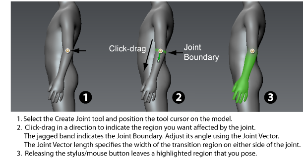
The fundamental component for posing a model in Mudbox is the joint. A joint is an item you place on a model to rotate, transform (and otherwise deform) neighboring components that you specify (arm, foot, leg, and so on). Much like a knee joint rotates to move the associated components of the lower leg (shin, foot, and toes), joints can be placed on a model to articulate it into a desired pose. That is, the individual vertices associated with a joint (with their associated faces) are moved as one combined unit or set.
When you create a joint, Mudbox will attempt to center it in the volume based on the location it is placed. This makes it a quick and easy process for positioning a joint from any vantage point within the 3D View and provides an initially good default placement in most situations. Joints can also be repositioned after their creation to provide a better deformation of the vertices.
Joints automatically have a user-specified region of influence (weighting) that determines how much or how little of the surrounding vertices on the model are affected whenever the associated model component is rotated or transformed about the joint. The region of influence usually diminishes or falls off with distance across the joint.
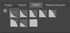
The falloff curve must be selected prior to joint creation from a set of presets in the Falloff tray. Otherwise, the falloff can be customized using the Weights tool. For more information, see Adjusting tool falloff.
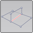
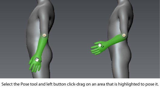
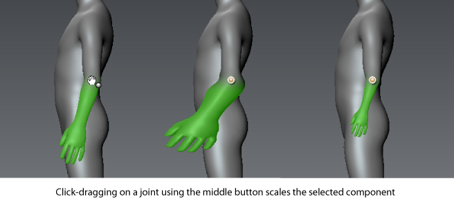
When the mouse/stylus is released, the region of the model affected by the joint is highlighted in green. This region is the component that moves, rotates or scales when you use the Pose tool. This highlighted region is known as the Weighted Region. To pose all of the model except the Weighted Region, press the Ctrl key while using the Pose tool.
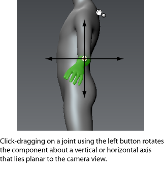
You can pose a joint you’ve created in Mudbox or joints that have been imported with a model you’ve imported. The current camera position plays an important role on the outcome of any pose operation. That is, all posing operations are performed in relation to it.
Click-dragging directly on a region that is highlighted using the left button causes the selected region to rotate in relation to a rotation axis that is normal to the current camera view.
To save a pose
- Manipulate your character into the pose you want to save.
- Do one of the following:
- Open the Poses window (Windows > Poses). (If you have more than one skeleton in your scene, select the skeleton you want from the window that appears.)
- Select a Skeleton in the Object List.
- In the Skeleton properties (or Poses window) click Save New Pose As.
- In the Save Pose As window that appears, enter a name for the pose and click Save Pose.
- Open the Poses window or Skeleton properties and select the pose you want from the Go To Pose drop-down list.
- In the Poses window or Skeleton properties, select the pose you want to update in the Go To Pose drop-down list.
- Transform the model into the updated position you want.
- Click Update Pose.